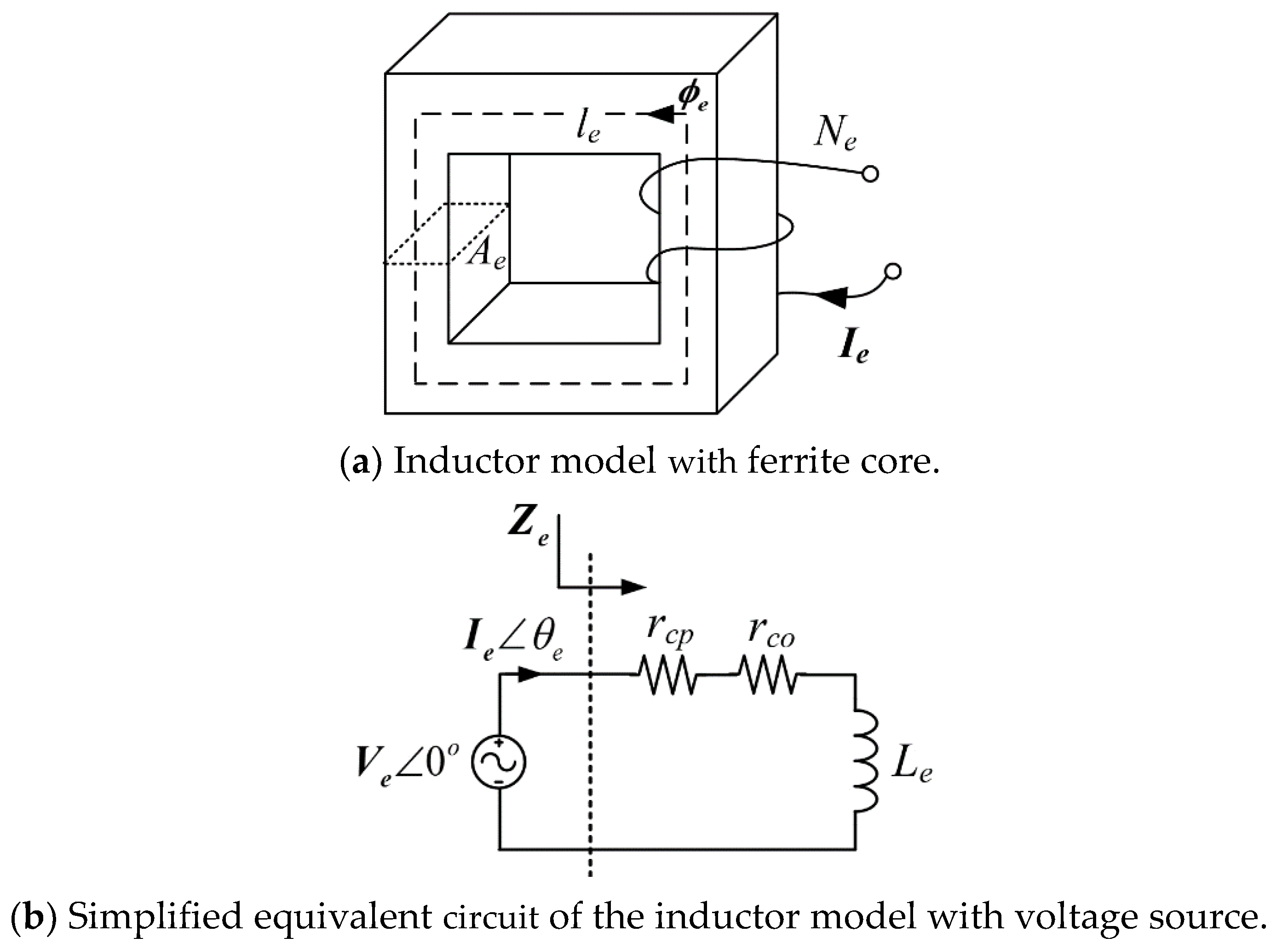

The E38/8/25 core can be bought in several different ferrite materials. Study and choose the ferrite material (stage 2 and 3) Hence, we have targeted a planar core-set. Another aim of this design is to keep the overall profile height as low as possible. On the right is how the core set and PCB will be constructed The copper PCB tracks will form the coil loops, and we may have to stack several small PCBs to get the right number of turns. It is shown using the blue line in the figure below: It is the average travel distance of the magnetic flux when two core halves are brought together. Highlighted in the red box is the core’s effective length (ℓ e) this is an important value for calculating the peak flux density.

The part number is E38/8/25, and two halves are needed to make a full core-set: The design we are using as the basis of this article is aiming for an inductance of about 1 mH, and the ferrite material that will be considered is a planar type made by Ferroxcube.

The process involves a sequence of steps requiring the use of several data sheets and, should the ferrite core need to be gapped, some degree of iteration. In this article, I’m going to take you through the standard ferrite core selection and design process used in applications such as a DC-to-DC converter or a power filter inductor.


 0 kommentar(er)
